One product family, six groove-count paths
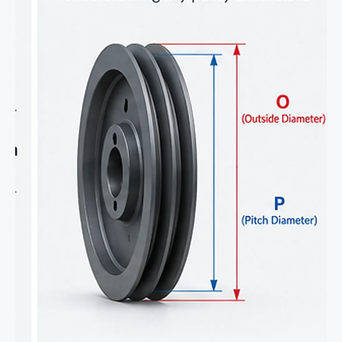
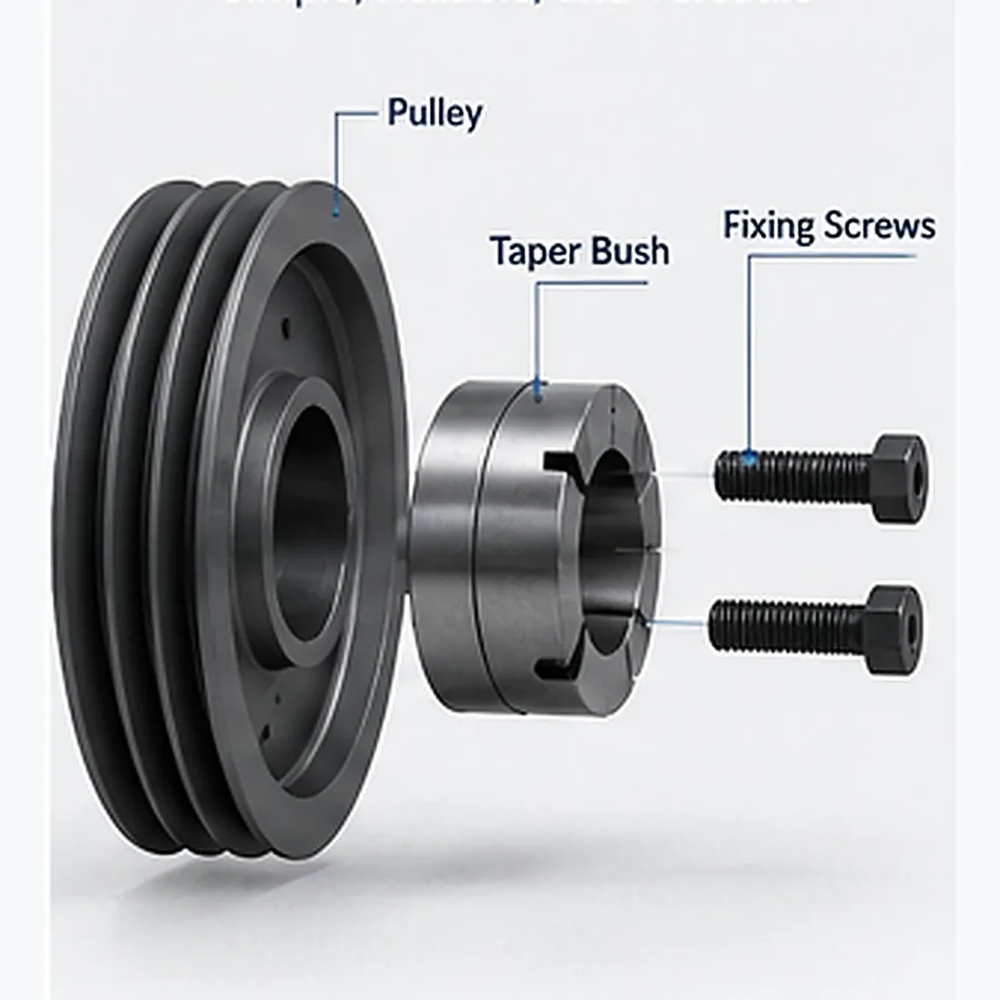
The SPA range is organised by active groove count because that gives maintenance and purchasing teams a clear first step without splitting the catalogue into dozens of thin diameter categories. Once the correct family is open, model pages provide the P and O references, construction type, taper-bush designation, maximum bore and letter dimensions.
That structure keeps a replacement search practical while preserving the model-specific differences that matter at the shaft and hub.
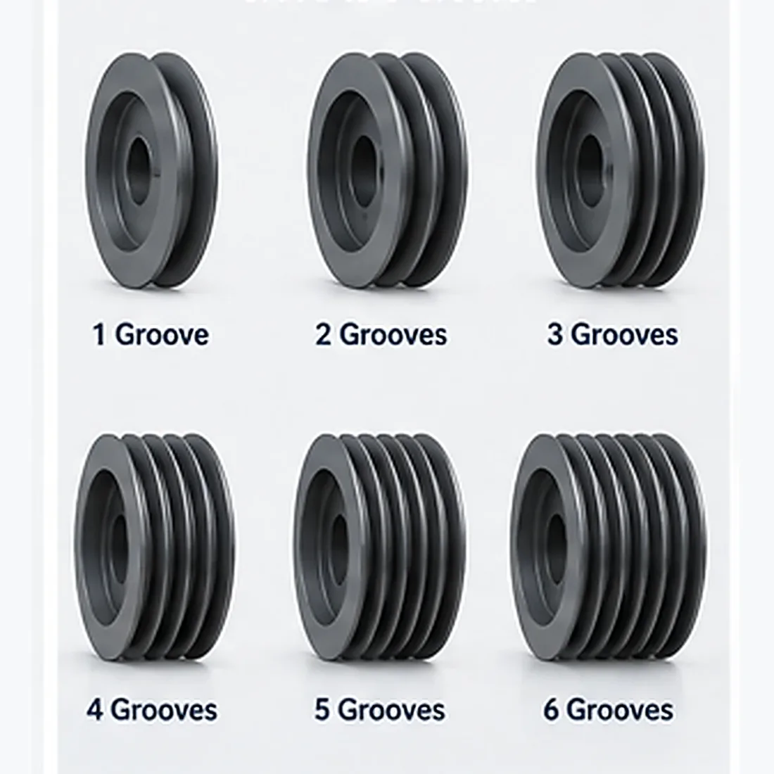
Browse SPA pulleys by active groove count
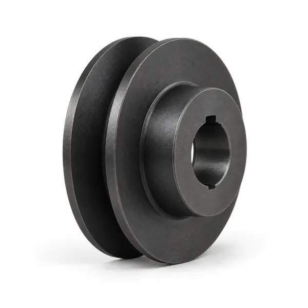
Pulley SPA 1 Alur
Bandingkan data P/O, semak belukar, dan konstruksi.
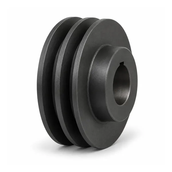
Pulley SPA 2 Alur
Bandingkan data P/O, semak belukar, dan konstruksi.
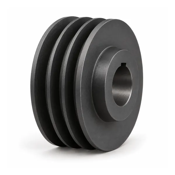
Pulley SPA 3 Alur
Bandingkan data P/O, semak belukar, dan konstruksi.
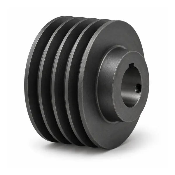
Pulley SPA 4 Alur
Bandingkan data P/O, semak belukar, dan konstruksi.
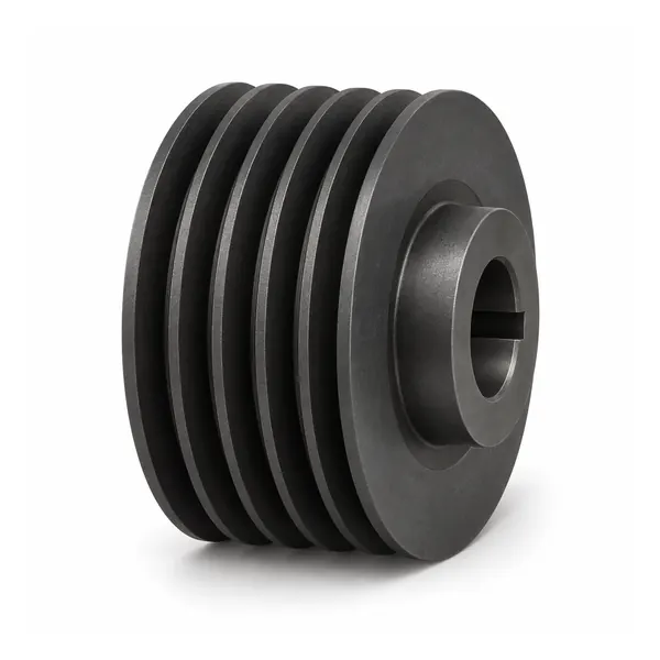
Pulley SPA 5 Alur
Bandingkan data P/O, semak belukar, dan konstruksi.
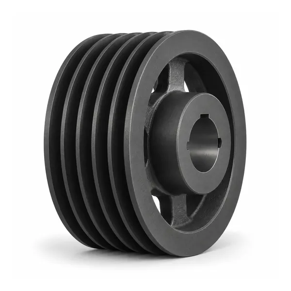
Pulley SPA 6 Alur
Bandingkan data P/O, semak belukar, dan konstruksi.
What changes from one SPA model to another
Groove count stays visible, but the complete technical identity also includes diameter references, mounting interface and construction details. Compare those fields together rather than choosing from product photography alone.
P and O
Keep the two diameter references distinct throughout the selection and RFQ process.
Taper bush and maximum bore
Use the bush designation with the actual shaft requirement. Maximum bore is a model limit, not the finished shaft size.
Construction type
The type determines which construction view should be used when checking hub arrangement and letter dimensions.
Match the drawing to the model construction
Hub arrangements change across the range. When axial position, guard clearance or removal space matters, use the technical view associated with the model construction type. Do not borrow a neighbouring drawing merely because the outside diameter is close.
If the model does not have an exact view available in the online library, include the full model and required interface data in the RFQ so the correct drawing can be confirmed.
Use different starting information for different jobs
For replacement work, begin while the drive is still assembled. Record the existing marking, groove count, belt, shaft and bush, and photograph the belt line before removal. For a new design, start from the required drive relationship, shaft, installation envelope and service access, then compare models inside the correct SPA family.
Both paths should end with the same result: a complete model identity and a clearly stated shaft interface.